Modifying low band cavities to 2 metres.
Low band (70 MHz) cavity filters are a long way from the amateur 6 metre band and the 2 metre amateur band frequency wise. To put them in either of these amateur bands requires considerable physical modification. There are several difficulties to be overcome and as there are several different types of filters, each requires a variation of what is presented here, but the basic conversion would apply. This web page is about reducing the length of the filters so they can be used in the amateur 2 metre band. One considerable problem is reducing the length of the centre resonator, as the outside tube has to be longer than the internal tube and this required considerable experimentation as to how to shorten the inner tube. Remember the outside tube prevents easy access to the internal tube to cut it. 70 MHz cavity filters. 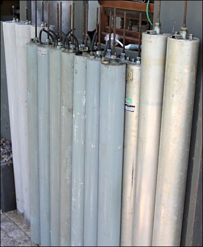 The wooden track to contain
the filter for working on
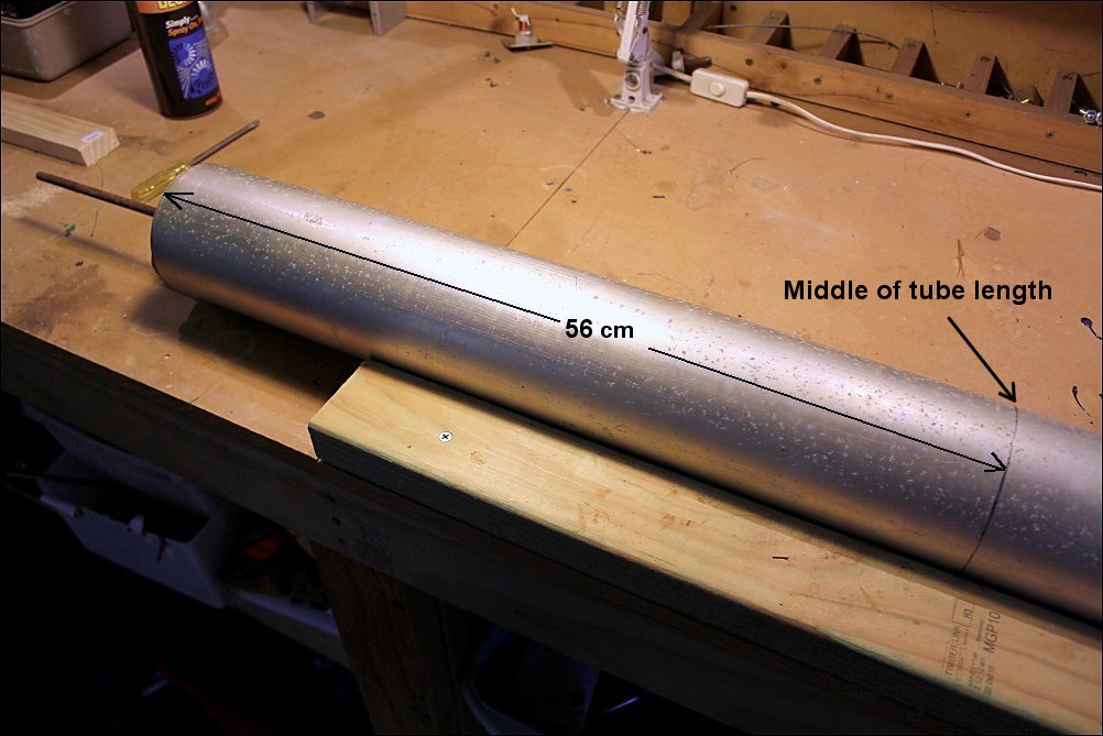
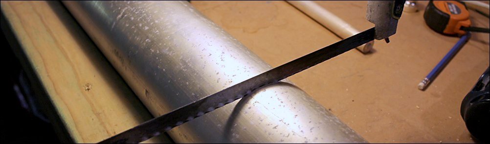
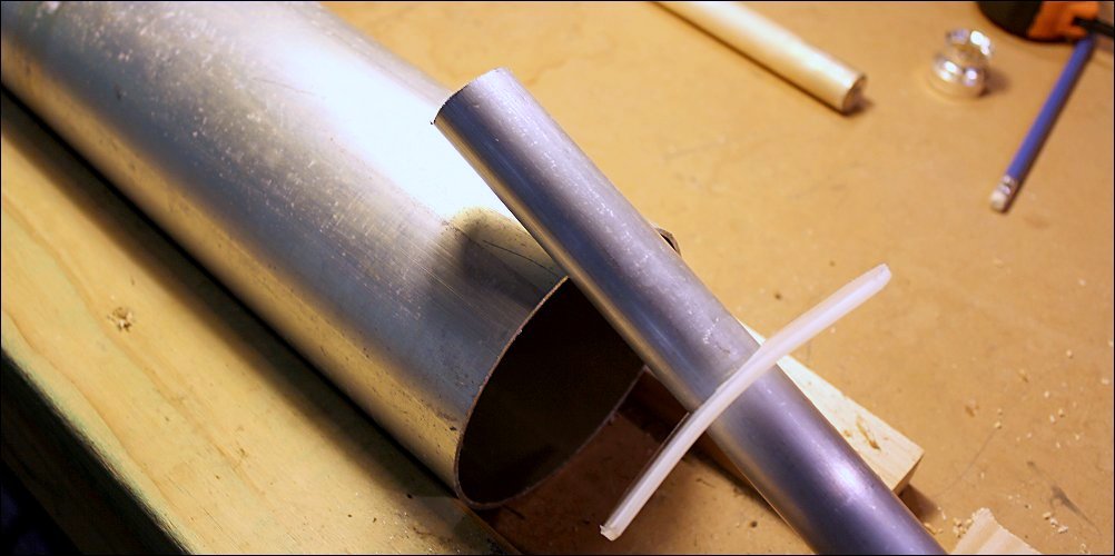
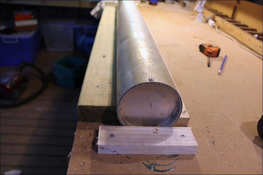 To cut the outer tube requires a marked out circle that is at 90 degrees to the length of the tube. This can be achieved by holding a pencil against the outer tube and rotating the tube. The low band outer tubes can be cut in half so as to make available the off cut outer tube for another 2m cavity filter. Note some low band cavity filters are longer but still a good idea to cut in half. They will be longer than the 56 cm as shown. 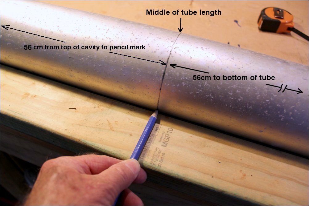 Ready for cutting
 Not having a lath, the only way to cut the outer tube is with a hacksaw. This is not as difficult as you may think. It took about 2 minutes to cut all the way round, rotating the tube as you cut. It is not possible, nor a good idea to cut straight through without rotating the tube, as the inner tube gets in the way and it is difficult to cut a good right angle cut. 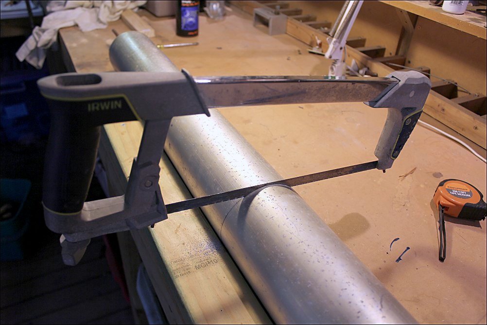 The outside tube cut all
the way round
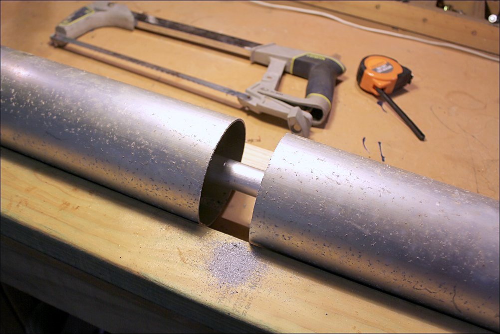 The lower outside bottom
tube removed
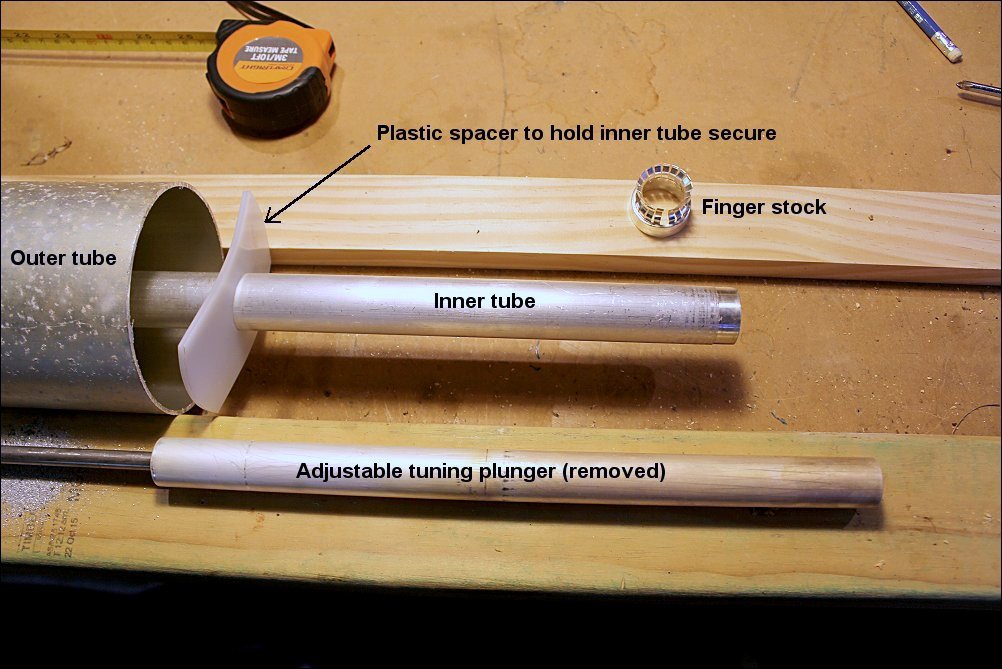
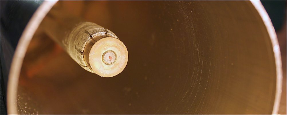
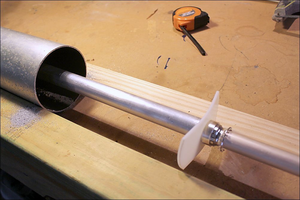 The bottom of the inner tube, the resonator, had a press fit ring and finger stock that makes the connection between the inner tube and the tuning rod. It was easy to tap off the finger stock ring to be used on the shortened centre resonator later. (Turned out it did not work more below) 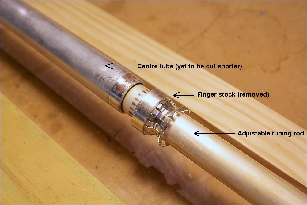 The centre adjustable
tuning plunger. This adjusts the resonant frequency of the cavity
filter by changing the length of the centre tube
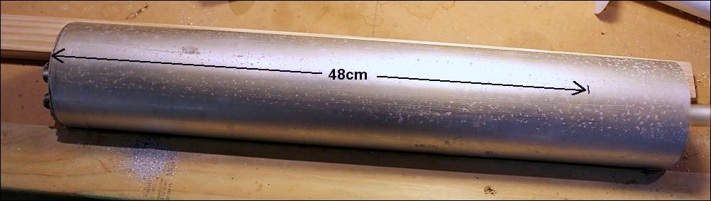
 Measure 48 cm from the top
of the now short outside tube and mark, resonates the cavity to about
150 MHz.
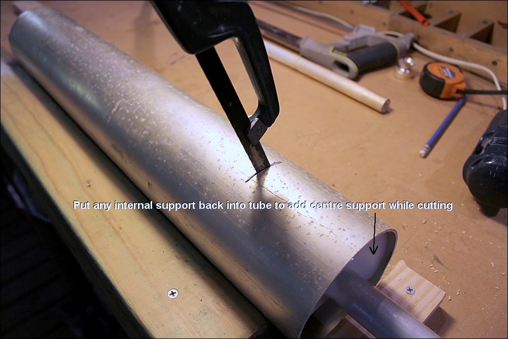
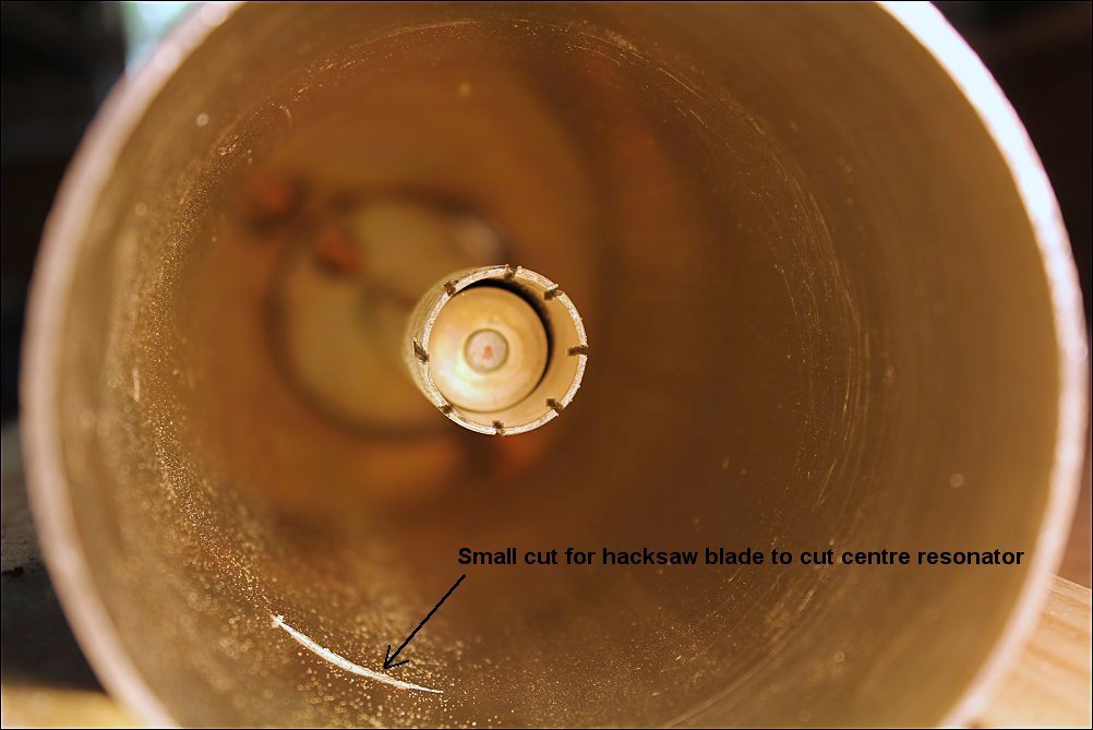
 This was the most difficult bit to figure out, how to shorten the inside centre resonator. Being completely surrounded by the outer tube and having to cut the inner tube some 9cm inside from the open end took a while to figure out. I even purchased a large drill but and tried drilling out the centre from the open end, but there was far too much vibration, it just would not work. What I decided to do was cut, at the 48cm point from the top of the cavity (a bit less than a 1/4 wavelength at 148 MHz), a slit that would allow a hacksaw blade to be inserted through the slit and cut the inside resonator tube. Slit cut at the bit less
than a 1/4 wave point
 Using a hacksaw blade held
with a hacksaw blade holder, cut through centre resonator tube
 Lower part of centre
resonator cut off
 We now have a 2 metre
cavity filter resonating about 150 MHz.
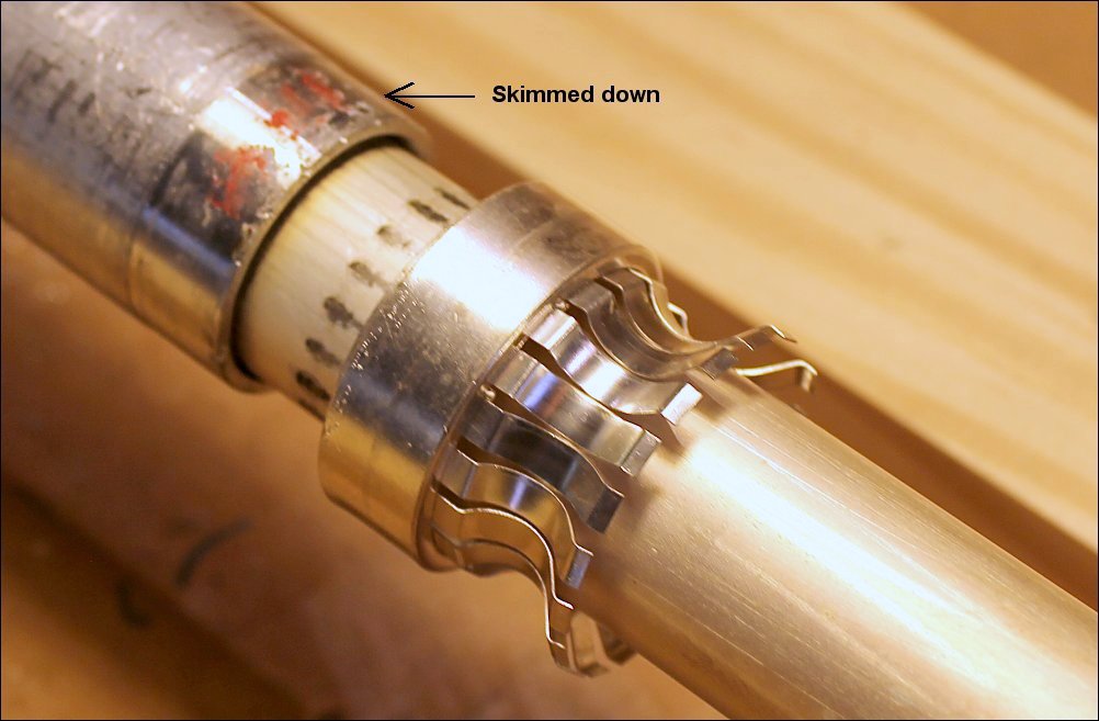
Original press fit of
finger stock onto the centre resonator. Note the tube had been skimmed
down on a lath. When the centre resonator tube is cut of course this
part of the tube is wider in diameter and it is difficult to reduce the
size of the inner tube inside the outer tube. Hence I found, even after
trying to file down the end of the inner tube, that I could not press
fit the finger stock. An alternative method of providing the connection
between the moving centre tunning plunger and the centre resonator is
shown below this photograph.
 As it proved too difficult to fit the finger stock and retaining ring back on the centre resonator, a series of about 1cm slots were cut in the centre resonator, ready to be squeezed slightly inwards and hence make the connection to the frequency adjusting plunger. This has been tried before and work. This is not a critical part of a cavity filter, as it is the high voltage low current part of the centre resonator. 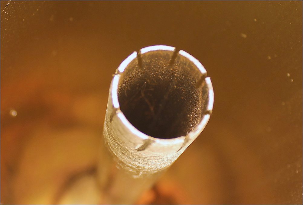 Insert the tuning rod from the bottom of the cavity filter all the way in, past the slots, before the slots cut in the centre resonator are squeezed slightly in. 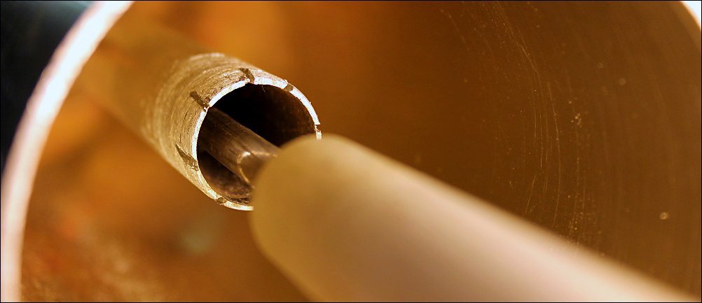 Centre tunning rod inside
centre resonator ready for slots in resonator to be slightly squeezed
inwards.
 Centre tunning plunger
screwed back into the squeezed in slots at the bottom of the centre
resonator. We are now able to adjust the cavity filters resonant
frequency.
 Now for the top end of the cavity filter
 This particular low band cavity filter has two N type connectors and two coupling loops. Not all cavity filters have this. Some have only one loop and are used in various ways not considered in this article. This cavity filter is a typical band pass band notch type and the C and L combination on the right of the photograph is connected between the two N type connectors. Adjustment of the C shifts the notch mainly with a small shift in the pass. The white wire connects them all together. It could be used perhaps in the 2 metre version but I'm not using them for this design, but separate L and C. The low band coupling
loops are way too big and need to be reduced in size (area) by about
half. Coupling loops are not critical in regards to their
shape, but critical in regards to their coupling to the centre
resonator, not only in the amount of coupling but both must have the
same coupling when compared to one another.
The coupling is even more important when using the filters in a band pass - band notch duplexer. Both the best band pass (minimum loss) and the band notch (maximum attenuation) inter relate to some degree and coupling effects the best result for both. The coupling loops must be identical
physically.
|